

 Page views: 78
  Date:Feb 20,2023


1.Objective
To test the frequency accuracy, negative impedance value, and drive power value of the crystal oscillator in use in the circuit; based on the matching results, determine the product specifications or determine whether the product specifications meet customer needs.
2.Scope of Use:
New product specification development; product specification verification.
3.Test Items:
Measurement of frequency accuracy, negative impedance, and drive power of the crystal oscillator in the circuit.
4.Measurement Method:
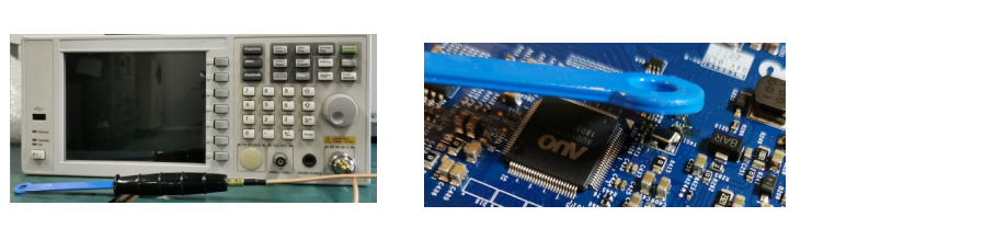
4.1 Frequency Accuracy Testing
Testing Equipment: Spectrum Analyzer (Agilent), Near-field Probe (Tek), 250B Network Analyzer. Test point: Near the crystal oscillator, no need to touch.
Testing Method: After setting the corresponding frequency on the spectrum analyzer, the near-field probe is placed near the crystal oscillator position to read the frequency value of the crystal oscillator in the circuit. Accuracy determination standard: The difference between the frequency on-board test value and the 250B test value is approximately <5ppm.
4.2 Negative resistance measurement:
Testing equipment: Oscilloscope (Tektronix DP03032), active probe (Tektronix TAP1500), variable resistor. Test point: the out terminal.
Testing method: Connect a variable resistor in series between the solder pad at the out terminal and the crystal oscillator. Adjust the variable resistor value to find the critical resistance value R at which the crystal oscillator stops oscillating and starts oscillating. When the circuit oscillates from start to stop, remove the variable resistor and measure the impedance value with a multimeter; add the crystal resonant impedance value to get the negative resistance value. Negative resistance = |-R| = R + RL, and RL = Rr * (1 + CO / CL) ^ 2 Rr = crystal resistance.
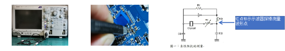
Judgment standard: Negative resistance is used to evaluate the oscillation circuit; usually, to maintain a stable oscillation loop, the negative resistance of the oscillation circuit should be at least 5 times the maximum specified resistance Rr.
4.3 Drive level measurement:
Test equipment: oscilloscope, current probe (CT-1), 250B network analyzer. Test point: measured at the out-terminal.
Measurement method: solder a wire to one end of the crystal oscillator and place the current probe as shown in Figure 2. Provide voltage to the PCB and observe the excitation current waveform on the oscilloscope. Measure the current passing through the quartz crystal, and place the current probe at point A as shown in Figure 1. If the waveform is a sinusoidal wave or similar, use I=lp-p/2√2 to calculate the effective value of the excitation current, and read the digital oscilloscope for the effective value. Calculate the drive power through the drive power formula. Drive power (p)=12-Rr. Note: The current (effective value) refers to the current passing through the quartz crystal during the operation of the oscillator, which is the excitation current measured on the actual oscillator circuit. Rr is the equivalent series resistance of the quartz crystal and is measured using the network analyzer.

To test the frequency accuracy, negative impedance value, and drive power value of the crystal oscillator in use in the circuit; based on the matching results, determine the product specifications or determine whether the product specifications meet customer needs.
2.Scope of Use:
New product specification development; product specification verification.
3.Test Items:
Measurement of frequency accuracy, negative impedance, and drive power of the crystal oscillator in the circuit.
4.Measurement Method:
4.1 Frequency Accuracy Testing
Testing Equipment: Spectrum Analyzer (Agilent), Near-field Probe (Tek), 250B Network Analyzer. Test point: Near the crystal oscillator, no need to touch.
Testing Method: After setting the corresponding frequency on the spectrum analyzer, the near-field probe is placed near the crystal oscillator position to read the frequency value of the crystal oscillator in the circuit. Accuracy determination standard: The difference between the frequency on-board test value and the 250B test value is approximately <5ppm.
4.2 Negative resistance measurement:
Testing equipment: Oscilloscope (Tektronix DP03032), active probe (Tektronix TAP1500), variable resistor. Test point: the out terminal.
Testing method: Connect a variable resistor in series between the solder pad at the out terminal and the crystal oscillator. Adjust the variable resistor value to find the critical resistance value R at which the crystal oscillator stops oscillating and starts oscillating. When the circuit oscillates from start to stop, remove the variable resistor and measure the impedance value with a multimeter; add the crystal resonant impedance value to get the negative resistance value. Negative resistance = |-R| = R + RL, and RL = Rr * (1 + CO / CL) ^ 2 Rr = crystal resistance.
Judgment standard: Negative resistance is used to evaluate the oscillation circuit; usually, to maintain a stable oscillation loop, the negative resistance of the oscillation circuit should be at least 5 times the maximum specified resistance Rr.
4.3 Drive level measurement:
Test equipment: oscilloscope, current probe (CT-1), 250B network analyzer. Test point: measured at the out-terminal.
Measurement method: solder a wire to one end of the crystal oscillator and place the current probe as shown in Figure 2. Provide voltage to the PCB and observe the excitation current waveform on the oscilloscope. Measure the current passing through the quartz crystal, and place the current probe at point A as shown in Figure 1. If the waveform is a sinusoidal wave or similar, use I=lp-p/2√2 to calculate the effective value of the excitation current, and read the digital oscilloscope for the effective value. Calculate the drive power through the drive power formula. Drive power (p)=12-Rr. Note: The current (effective value) refers to the current passing through the quartz crystal during the operation of the oscillator, which is the excitation current measured on the actual oscillator circuit. Rr is the equivalent series resistance of the quartz crystal and is measured using the network analyzer.